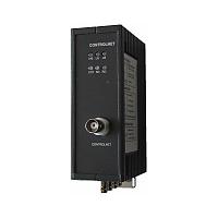
Controlnet Fiber Optic Converter
Introduction
HFD-FO-CL ControlNet Fiber Optic Converters are designed to be used in optical CONTROLNET field bus networks . They enable electrical CONTROLNET interfaces to be converted into optical interfaces.
The ControlNet Fiber Optic Converter can show the different methods for connecting the modules, and the optical ranges of port
By profiting from the familiar advantages of optical transmission technology, the modules can be integrated into existing CONTROLNET field bus networks. A complete CONTROLNET field bus network with modules in point to point, line, star or ring topology, and an arbitrary combination of these, can also be built up.
The redundant ring is also supported to the ControlNet Fiber Optic Converter, thereby increasing the fail-safety of the field bus network.
The device(ControlNet Fiber Optic Converter) is powered by 24V DC voltage. A redundant feed increases operational safety.
The electric port is a BNC socket. An electrical coax segment with the CONTROLNET standard can be connected to this port by drop cable.
The optical fibers are connected using ST connectors.
6 multicolored LED indicate the current operating status
Signal regeneration
The modules regenerate the signal form and amplitude of the data received. This allows up to 50 CONTROLNET to be cascaded.
Segment monitoring at the cable port
Each receiver monitors the cable bus segment connected to it for faulty frames or continuously busy networks. If faulty frames are received by the receiver, or if the network is busy for longer than the maximum permitted send time, forwarding of the received signals is blocked until frames can be received again correctly, or if no signal is received 0.5s.
Segment monitoring at the optical line
Each receiver monitors the optical line port connected to it for recive framesand status. If faulty status are received by the receiver, or no single for recived, forwarding of the received signals is blocked until the port status is ok,frames can be received again correctly.
Specifications:
| Voltage/power supply |
|
| Operating voltage |
12 V to 30 V DC, typ. 24 V, |
| Current consumption |
typ. 120 mA@24V |
| Signaling contact |
Max .switch DC24V@2A or AC125@0.2A |
| Signal transmission |
|
| Transmission rate |
CONTROLNET rate |
| Bit error rate |
< 10-9 |
| Delay time valus(NS2504xx) |
930ns/2 station |
| Delay time valus(NS2501xx,in line topology) |
170ns * (N -2) + 1100ns
N = the stations between the two nodes
|
| Delay time valus(NS2501xx,in ring topology) |
170ns * N + 1100ns
N = all stations in the network |
| Retimer (Electrical port) |
|
| Input |
Signal distortion ±30 % |
| Bit length |
±0.12 % |
| Output |
Mean bit length ±0.01 % |
| Cascade modules |
50 |
| Electrical port |
|
| Input/output signal |
CONTROLNET |
| Isolate voltage |
>= 1500VDC |
| PIN assignment |
BNC |
| Optical ports |
|
| Wavelength |
1310 nm |
| optical power |
|
| – in glass fiber 9/125um |
-9dBm – -18 dBm |
| – in glass fiber G 62.5/125 |
-13 dBm – -20 dBm |
| Receiver sensitivity |
-34dBm |
| Transmission distance |
|
| –with glass fiber 9/125um |
0 – 20,000 m (0.3 dB/km) |
| – with glass fiber G 62,5/125 |
0 – 3,000 m (2.0 dB/km) |
| Connector |
ST |
| Electromagnetic compatibility (EMC) |
|
| Limit class B (EN 55022) |
EN 61000-4-2
EN 61000-4-3 |
| Burst: |
|
|
On power supply lines
shielded RS 485 bus lines
|
±2 kV (EN 61000-4-4) |
| Surge |
|
| Power lines,Shielded RS 485 lines |
±1 kV symmetrical,±2 kV asymmetrical (EN 61000-4-5)
|
| Others |
|
| Ambient temperature |
-25 °C to +75 °C |
| Storage temperature |
40 °C to +85 °C |
| Relative humidity |
<95 %, non-condensing |
| Protection class |
IP 40 |
| Dimensions (W x H x D) |
62 x 132 x 120 mm |
| Weight |
approx. 600 g |
| 















 ControlNet Fiber Optic Converter